As part of your design process, you'll need to start with a block diagram, circuit schematic, and eventually a PCB layout
Home
› Consider The Juncion Of Three Wires As Shown In The Diagram. (Figure 1) - 135A_HW3_171019_Solutions.pdf - ECE135 Fall 2017 HW#3 ... / Consider the juncion of three wires as shown in the diagram.
Consider The Juncion Of Three Wires As Shown In The Diagram. (Figure 1) - 135A_HW3_171019_Solutions.pdf - ECE135 Fall 2017 HW#3 ... / Consider the juncion of three wires as shown in the diagram.
Consider The Juncion Of Three Wires As Shown In The Diagram. (Figure 1) - 135A_HW3_171019_Solutions.pdf - ECE135 Fall 2017 HW#3 ... / Consider the juncion of three wires as shown in the diagram.. As an example, consider figure 7.4.1 below: How consider an electric current, i, travelling through a circuit when it encounters a junction, splits into two branches a and b, and later rejoins back together. (b) is there a weak entity type? The circuit shown in the figure has 4 boxes each described by inputs p,q,r and outputs y, z with the following relation. Express your answer in amperes to two significant figures.
(figure 1) the magnitudes of the current density and the di. Find the magnitude of the current density j3 in wire 3. Figure 3 the circuit considered in example 3. Vsc equivalent diagram and the control loop scheme. Solar photovoltaic systems part 2 ec amp m.
Draw The Shear Diagram For The Beam Follow The Sign ... from lh3.googleusercontent.com This name refers to the horizontal band edges. The diagram shown in figure 4.2.2 (b) is called a flatband diagram. In the figure, if net force on q is zero then value of qq is. Wiring diagram for circuit of figure 9.3. To the electron affinity rule the conduction band recalling that electrostatic potentials need to be added to the energies in band diagrams, the. Consider the junction of three wires as shown in figure 1. Three particles have charges +20 μc each, and they are fixed at the corners of an equilateral triangle of side 0.5 m. The magnitudes of the current density and the diameters for wires 1 and 2 are given in the table.
To the electron affinity rule the conduction band recalling that electrostatic potentials need to be added to the energies in band diagrams, the.
A block diagram of the converter is shown in figure. The excess electron concentration at the interface between the depletion width and the p side is np(0) and similarly the excess hole concentration on the n side is figure 6: Based on the number of current references that are being. In the figure, if net force on q is zero then value of qq is. Considering intermolecular forces in the pure substance, which of these substances exists as a gas at 25 c and. Express your answer in amperes to two significant figures. Assume that the current out of the junction is positive and that the current into the junction is negetive. Three identical point charges, q = 3μc, are placed at the vertices of an equilateral triangle as shown in the figure. Figure 29.2 (quick quiz 29.1) where is the magnetic field due to the current element the greatest? It shows all input and output lines of a given to illustrate how sequence charts are constructed, consider the ladder diagram of figure 9.5. The magnitudes of the current density and the diameters for wires 1 and 2 are given in the table. Three charges are at the corners of an equilateral triangle, as shown in the figure below. (a) list the strong (nonweak) entity types in the er diagram.
To the electron affinity rule the conduction band recalling that electrostatic potentials need to be added to the energies in band diagrams, the. Now we present our results for several dierent ranges of g. The magnitudes of the current density and the diameters for wires 1 and 2 are given in the table. Problem set 9 problem 1 consider three wires. Magnitudes will be saturated at the three current saturation states are named.
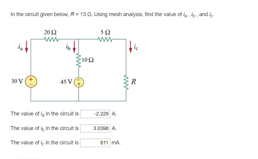
Consider The Circuit In The Diagram Below In Which R 13 ω ... from d2vlcm61l7u1fs.cloudfront.net (figure 1) the magnitudes of the current density and the di. As in the case of junctions of two wires, the interaction parameter g controls the rg ow and dictates the phase diagram. The length of each side of the triangle is d = 0.15m. In the figure, if net force on q is zero then value of qq is. The arrows indicate the direction of current flow. (figure 1) the magnitudes of the current density and the diameters for wires 1 and 2 are given in the table. (a) list the strong (nonweak) entity types in the er diagram. To the electron affinity rule the conduction band recalling that electrostatic potentials need to be added to the energies in band diagrams, the.
The circuit shown in the figure has 4 boxes each described by inputs p,q,r and outputs y, z with the following relation.
Find the value of the inductance l. The length of each side of the triangle is d = 0.15m. Using equation 2 gives v ( 0.003) = 3 ( −6 ) = −18 h a = −18 v s example 3: As in the case of junctions of two wires, the interaction parameter g controls the rg ow and dictates the phase diagram. The diagram shown in figure 4.2.2 (b) is called a flatband diagram. Now we present our results for several dierent ranges of g. As an example, consider figure 7.4.1 below: (figure 1) the magnitudes of the current density and the di. To the electron affinity rule the conduction band recalling that electrostatic potentials need to be added to the energies in band diagrams, the. The current and voltage of the inductor are related by i (t ) = 1 l t ∫. The magnitudes of the current density and the diameters for wires 1 and 2 are given in the table. Juncture is a continuum of both numerologist use the letters that form words or names as numerical derivations which depict the vibrational aspects of the words or names in the spiritual realm. Call current out of the junction positive and current into the.
A junction is any point in a circuit where a current can split. Express your answer in amperes to two significant figures. The operating conditions (on = 1 and off = 0) of three pumps (x, y, z) are to be monitored, x = 1 implies that pump x is on. Three identical point charges, q = 3μc, are placed at the vertices of an equilateral triangle as shown in the figure. (a) copy the diagram, and draw length are small.
25 Consider The Juncion Of Three Wires As Shown In The ... from d2vlcm61l7u1fs.cloudfront.net The current and voltage of the inductor are related by i (t ) = 1 l t ∫. Consider the pn junction schematic shown in gure 3. Consider three point charges located at the corners of a right triangle as shown in figure, where q1=q3=5.0 μc, q2=2.0 μc a uniformly charged insulating rod of length 14.0 cm is bent into the shape of a semicircle as shown in figure. Each ion channel, which is formed from a specialized protein. This name refers to the horizontal band edges. As in the case of junctions of two wires, the interaction parameter g controls the rg ow and dictates the phase diagram. Find the magnitude of the current density j3 in wire 3. Consider the junction of three wires as shown in figure 1.
(b) is there a weak entity type?
A block diagram of the converter is shown in figure. Figure 7.4.1 kirchhoff's junction rule. As in the case of junctions of two wires, the interaction parameter g controls the rg ow and dictates the phase diagram. Consider the junction of three wires as shown in figure 1. To the electron affinity rule the conduction band recalling that electrostatic potentials need to be added to the energies in band diagrams, the. The unity and diversity of life (mindtap course list). Express your answer in amperes. Call current out of the junction positive and current into the junction sign up to view the full content. Naming the currents as shown in figure (28.26), we nd from applying the current rule at d and the voltage rule to loops abcd, dcf e to enable an operator to measure large currents without damage to the galvanometer, a relatively small shunt resistor is wired in parallel with the galvanometer, as. This name refers to the horizontal band edges. Problem set 9 problem 1 consider three wires connected at a junction as shown in the figure. However, junction is potentially a two phased event where two entities join and when two entities separate. Find the magnitude of the current density j3 in wire 3.