How To Read Wiring Diagram : How To Read A Schematic Learn Sparkfun Com - A relay is an electrically operated switch.. With the large number of pages and sections in the ewd, the fastest way to find the wiring diagram or information you need is to use the table of contents. Wiring diagram 30 15 no. Pictorial diagram is a picture or sketch of the components of a. Now that you're familiar with the common symbols used in schematic diagrams, let's take a look at how to read wire connections and wire crossings. We begin with a basics fuel pump & relay diagram
On diagram 1, cable 1099 goes to component 30e07. At first glance the repair diagram may not convey how the wires use many colors and diameters. Often when working on appliances, it is necessary to read these diagrams when there is an electrical problem with the appliance you are working on. Refer to the figure, an electrical wiring diagram is surrounded by the rectangular box. Circuit drawings and wiring diagrams description successfully performing electrical work requires the ability to read and interpret many different types of drawings and diagrams.
How To Read And Understand An Electrical Schematic from www.javelin-tech.com The power supply is shown at the top and the earth at the bottom to facilitate understanding of the current flow. In part 1 of this series, you've learned how to read and understand a wiring diagram of an. Reading diagrams on multiple pages. Despite different standards of these types of drawings, you'll learn using actual industrial drawings and some plc wiring best practices. Electrical wiring diagrams are included in aircraft service manuals and specify information, such as the size of the wire and type of terminals to be used for a particular application. At first glance the repair diagram may not convey how the wires use many colors and diameters. They show the diameter of each wire using a label placed at some point along side its drawn line (1) (0.8). A resistor will be represented with a series of squiggles symbolizing the restriction of current flow.
The box is marked with the numbers and alphabets followed by the page number.
If an electrician misinterprets a So to sum it all up, here is what we learned in this article: Wire diagrams use wire color codes to identify the color of wire being used to connect different electrical components within the circuit. But sometimes, designers make some exceptions to have a better layout such as this page. Reading diagrams on multiple pages. At first glance the repair diagram may not convey how the wires use many colors and diameters. Electrical wiring diagrams are included in aircraft service manuals and specify information, such as the size of the wire and type of terminals to be used for a particular application. The images below show the schematic symbols for wires when they are physically connected in a circuit. This instructable will show you exactly how to read all those confusing circuit diagrams and then how to assemble the circuits on a breadboard! A relay is an electrically operated switch. Some wire colors are specific to the wire's use such as black, white, red, and green, while others are used for component connection and change function from one circuit to another. These can take some effort to locate on fold out map type diagram. On more complicated electrical systems or electronic modules, diagrams can quickly become filled with tons of lines and symbols making it hard to read for the user.
Some cables start on one diagram and finish on another. A relay is an electrically operated switch. This is what we draw using autocad electrical. Understanding circuit symbols and components is another one of the basic building blocks needed to become an electrician. On diagram 1, cable 1099 goes to component 30e07.
Wiring Diagram Reading How To Read Circuit Diagrams 4 Steps Instructables In Order To Effectively Use Diamlerchrysler Wiring Diagrams To Diagnose And Repair A Wiring Diagram 3 Way Switch from tse4.mm.bing.net They show the diameter of each wire using a label placed at some point along side its drawn line (1) (0.8). In part 1 of this series, you've learned how to read and understand a wiring diagram of an. So to sum it all up, here is what we learned in this article: Learn how to wire a 4 or 5 pin relay with our wiring diagrams and understand how relays work. In addition to the symbols, every component on electrical schematics has a unique name and value, which further helps to identify what it represents.component names are usually a combination of one or two letters and sometimes a number. On more complicated electrical systems or electronic modules, diagrams can quickly become filled with tons of lines and symbols making it hard to read for the user. Wire diagrams use wire color codes to identify the color of wire being used to connect different electrical components within the circuit. Wiring diagram 30 15 no.
I have elsawin, which i have slowly learnt, the only part that i cant understand is for some earth circuits it says for example 410.
Wire diagrams use wire color codes to identify the color of wire being used to connect different electrical components within the circuit. Wires are represented by lines, and connections are represented by dots. Electrical wiring diagrams are included in aircraft service manuals and specify information, such as the size of the wire and type of terminals to be used for a particular application. Some wire colors are specific to the wire's use such as black, white, red, and green, while others are used for component connection and change function from one circuit to another. Refer to the figure, an electrical wiring diagram is surrounded by the rectangular box. A car wiring diagram is a map. Automotive wiring diagrams and electrical symbols. A node is simply a filled circle or dot. Most symbols used on a wiring diagram look like abstract versions of the real objects they represent. Now that you're familiar with the common symbols used in schematic diagrams, let's take a look at how to read wire connections and wire crossings. This is what we draw using autocad electrical. Earth connection 1 in main wiring harness, do you know how to find this earth location,, where as you know most regular earths on the diagrams such as 605 tells you where it is located,, on top of end of steering column. They show the diameter of each wire using a label placed at some point along side its drawn line (1) (0.8).
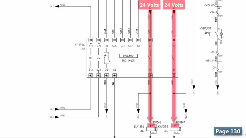
For example, a switch will be a break in the line with a line at an angle to the wire, much like a light switch you can flip on and off. It goes exactly the same for the other switches that we have here as well. Where this occurs the cable ends with an arrow and then the component the cable goes to is listed. The box is marked with the numbers and alphabets followed by the page number. A car wiring diagram is a map.
Wiring Diagrams Explained How To Read Wiring Diagrams Upmation from upmation.com Wires are represented by lines, and connections are represented by dots. So this is how easy it is to read the wiring diagram for a control panel. Reading diagrams on multiple pages. Most symbols used on a wiring diagram look like abstract versions of the real objects they represent. Some cables start on one diagram and finish on another. Circuit diagrams or schematic diagrams show electrical connections of wires or conductors by using a node as shown in the image below. These symbols are standardized, allowing quick recognition of various components. The message in the name determines the type of component, every component's name on an electrical schematic should be unique.
With the large number of pages and sections in the ewd, the fastest way to find the wiring diagram or information you need is to use the table of contents.
The images below show the schematic symbols for wires when they are physically connected in a circuit. Reading diagrams on multiple pages. In addition to the symbols, every component on electrical schematics has a unique name and value, which further helps to identify what it represents.component names are usually a combination of one or two letters and sometimes a number. If an electrician misinterprets a Use the legend to understand what each symbol on the circuit means. Understanding circuit symbols and components is another one of the basic building blocks needed to become an electrician. Electrical wiring diagrams are included in aircraft service manuals and specify information, such as the size of the wire and type of terminals to be used for a particular application. We begin with a basics fuel pump & relay diagram Despite different standards of these types of drawings, you'll learn using actual industrial drawings and some plc wiring best practices. Circuit drawings and wiring diagrams description successfully performing electrical work requires the ability to read and interpret many different types of drawings and diagrams. Block diagram use as troubleshooting complex electrical and electronic systems. Knowing how to read circuits is a very useful skill that will help you out all the time. Reading a wiring diagram for appliance repair.